
Transmission FAQ's
The transmission tips and FAQ's are divided into sections: C4, C6, FMX. AOD, T-5, Ford transmission pan ID, Ford transmission installation tips and General Powerglide Info. More information is included with the C4 and C6 videos.
C4 Automatic Transmission
A little C4 History
The C4 transmission came out in 1964 and ran through 69 without many changes. In 1970, the C4 was upgraded with a larger input shaft and other beefer parts. More than half of the newer C4 parts are not interchangable with the earlier version. The early C4's can be identified by seeing a vent tube above the rear servo. 70 and later C4's have the vent (giggle pin) on top of the extension housing. 1981 was the last year for the C4 and in 82 the C5 was introduced which is a modified C4. It ran through 1986 and it's main upgrade was a lockup converter along with a better lubrication system.
General C4 Transmission Info
1. Be careful when swapping C4 and C5 trannnies. C5s are normally about one inch longer, (deeper bell housing because of the larger converter) which may make the driveshaft the wrong length.
2. The pan filled type large bell housing cant be installed on a small housing case filled type case. However normally a small bell housing can be installed on a pan filled type case. Remember the bulge on top of the pan fed case could cause floor pan clearance concerns.
3. Never use solvent to clean the clutches or bands. They can be wiped off with clean rag and soaked in ATF fluid and reused. If there is contamination on the clutches or bands, replace them. You probably should replace them on an overhaul anyway.
4. Use the fluid recommended by the overhaul kits manufacture. Ford used type F in all C4s and type H (Dextron III/ or Mercon) in the C5s. By the late 70s, the Ford recommended Dextron/Mercon when overhauling. Most kits can use either fluid.
5. When installing the valve body gasket, be sure that no holes are covered on the separator plate.
6. The large bellhousing/pan fed C4s are normally find in truck, vans, big bodied cars (Galaxy, Torino etc.) and cars with larger engines. Small bellhousing/case fed C4s are in the small cars (Mustang, Granada, Pinto, Fairmont, etc.) with smaller engines but there are exceptions to all of this.
7. Intermediate servos come in many sizes. The H servo has the largest apply side area and is found in most trucks. This servo is a good upgrade for a HiPo application.
8. Be careful when swapping out valve bodies. There are some early 70s valve bodies that have an extra valve body to case bolt. 64 to 66 valve bodies are the dual range type for shifters using P-R-N-D2-D1-L and 67+ v.b. are for the select shift type P-R-N-D-2-1.
9. You may find a yellow plastic plug with an o-ring around it in the pan. Its a shipping plug that was pushed into the pan when installing the dip-stick tube at the factory. Throw it away.
10. 64 to 69 input shafts are .789 OD and have 24 splines on both ends. 70+ shafts are .839 OD, have 26 spline on the converter end, 24 spline on the clutch end and this end is also shorter. Beware, theres an oddball shaft in some 70 models that are 26 spline on both ends.
11. If you have trouble getting the bellhousing flush with the engine block during installation or cant turn the flywheel after bolting up, the converter may not be all the way in the pump. The converter must engage the input shaft, stator support and pump gear lugs. With the converter installed properly, the converter hub will be deeper than the straight edge surface of the bell housing. With the transmission bolted tight to the block, you should be able to wiggle the converter stud easily in the flywheel. Note; If the engine has been changed or a stick shift to automatic swap is preformed, be sure the pilot bearing is removed from the rear of crankshaft.
C6 Automatic Transmission
Q. Whats that plastic plug in the oil pan?
A. The plug is installed in the dipstick tube hole at the factory to hold the full load of fluid in the pan. When the dipstick tube is installed on the assembly line the plug is simply knocked down into the pan. You can throw the plug away.
Q. Which way does the sun gear install in its input shell?
A. The short teeth of the sun gear goes to the inside of the input shell and the long teeth faces the outside. Dont forget to install the input shell washer on the outside of the shell before installing sun gear retaining ring.
Q. When I draw up the transmission to the block, why cant I turn the crankshaft?
A. The torque converter was not installed all the way into the pump. The converter must engage the input shaft, stator support and pump gear lugs. With the converter installed properly, the converter hub will be deeper than the straight edge surface of the bell housing. With the transmission bolted tight to the block, you should be able to wiggle the converter stud easily in the flywheel.
Q. Do I need a special tool to adjust the intermediate band?
A. No, just loosen the lock nut and screw in the adjusting stud until its good and snug with a short 5/16 open end wrench (which will be close to the spec. of 10 lb.ft.). Then loosen stud 1 ½ turns and tighten down lock nut.
Q. Which way does the modulator valve go into the case?
A. Orient the valve so that the 2 machined lands go into the case first with long shaft end facing out. Then install the modulator pin (looks like a short finishing nail), and finally the modulator diaphragm.
Q. Which way does the input shaft go in?
A. The long spline must be installed first with the short spline going to the converter. 1967 and later models will also have a different number of spline teeth on the clutch side. The 66 model has 31 teeth on both ends.
Q. Where does that forward clutch wave spring go?
A. If your working on a late 76+ C6 theres a wave spring to soften the drive gear engagement. The installation is; First install the lower pressure plate (curved side down), then the wave spring, then a steel plate, then a fiber plate, steel plate etc. ending with the thick pressure plate and snap ring on top.
Q. When I unbolted the one-way clutch race, I couldnt find the snap ring for the piston spring retainer.
A. If your working with a late 80s unit, there may not be a snap ring. These units ( after trans. build date 4,29,86 ) sometimes use a spring retainer with a smaller ID., which seats behind the one-way clutch race eliminating the need for a snap ring.
Q. Why does my 73 model C6 modulator have two vacuum hoses?
A. 73 was the first year for EGR valves. It was found that when the EGR opened, intake vacuum dropped causing later shifts. Adding the inner vacuum line which comes from the EGR, helped rebalance the shift points. Normally the inner (smaller) vacuum hose can be plugged off and the port on the modulator left open with no ill effects.
Q. Whats that black hard rubber sleeve on the output shaft at the inner end of the splines?
A. This is an anti-grunt bushing used to reduce slip yoke pop on acceleration. It really didnt work so its best to simple remove it.
Q. After installing an E4OD wide gear set, the engine revs too high between shifts at wide open throttle, why?
A. The engine is now turning a higher rpm at the same road speed so the governor is sending a lower pressure (causing later shifts). Changing to a low rpm governor used on inline 6 cyl. trucks or just removing the kick down linkage sometimes helps.
Q. My one-way clutch race is in good shape. Can I replace the #9 thrust washer with a needle bearing and still use the old one-way race?
A. No, the old race is too thick (1.090). The early single race needle bearing must be used with a 1.045 one-way clutch race and the newest double race needle bearing is used with the 1.015 thick one-way clutch race.
Q. Can the shift speed and firmness be adjusted?
A. Yes to a point. Most modulator diaphragms have an adjustment screw through the vacuum tube hole. Screw clockwise for later/firmer shifts and counterclockwise for earlier/softer shifts. However if more than two or three turns dont get what you want, you may have other problems.
Q. After overhauling my C6, the shift linkage will not line up with the shift lever.
A. The C6s shift lever may be upside down. The lever can be installed 180 degrees from the stock position. Always check the lever orientation before removing from case.
FMX Automatic Transmission
1. Although there were a number of differences or changes made during the FMX production, the most noteworthy are, going from ridged the flex front band, changing from screen type to fabric type filter, minor changes to valve body and longer output shafts on some Lincolns.
2. The newer style fabric filter can replace the older style screen filter. However, the two filters use different tangs and flange retainers. Therefore you should only change to new style filter if it comes with a new retainer parts.
3. Most FMXs will have a chamfered one-way/center support to make the planetary installed easily. However, there were some units without that chamfer, therefore, the one-way roller clutch must be installed on the center support race first. Then the planetary can be installed onto the race by turning it counter clock wise. Unfortunately it can be difficult to get the rollers installed in the planet carrier. It will be necessary to carefully push each roller into the planet carrier as its rotated CCW.
4. There are lots of metal tubes used in the FMX and they are just pressed fit. In most cases you only need to press them in by hand, however, I find a little tap with a plastic hammer is helpful. Be very careful when tapping as the tubes will bend quite easily. Once bent, in most cases they can not be straightened. Therefore be gentle.
5. If the pan on the transmission has never been removed, the shipping plug may still be in the pan. If so, simply throw it away since it no longer serves a purpose.
6. The FMX production ran from 1968 to about 1981 however, they were very rarely used after 1978 for a number of reasons but mainly because of the need for weight reductions to achieve better fuel economy.
AOD Automatic Transmission
1. The pre-88 AOD should not be used for serious HiPo or Drag race use. The lubrication system is not up to the job (the output shaft is the main concern). 88 and later is a better choice and in many cases an 88+ output shaft can be installed in an older AOD to upgrade.
2. The number one cause of failure in a stock or racing transmission is heat. Installing a quality aux. fluid cooler after the in-radiator cooler is a good idea and a must if you have a high-stall converter. Also use the fluid recommended by the overhaul kits manufacture. Ford Mercon (or Dextron III) is normally used in all AODs. Ford now recommends MerconV for the AOD/4R70W.
3. All AODs have the same small block bell housing bolt pattern as well as the 11-½ converter bolt circle. Normally engines with a C4/C5 11-½ bolt circle flex plates can bolt to the AOD.
4. You may find a yellow plastic plug with an o-ring around it in the pan. Its a shipping plug that was pushed into the pan when installing the dip-stick tube at the factory. Pitch it.
5. You should tear down your AOD and inspect before buying any parts. It may already have upgraded parts or damaged parts that you may not be aware of which will dictate what overhaul kit and extra parts to get.
6. If you have trouble getting the bell housing flush with the engine block during installation or cant turn the flywheel after bolting up, the converter may not be all the way in the pump. The converter must engage the two input shafts, stator support and pump gear lugs. With the converter installed properly, the converter hub will be deeper than the straight edge surface of the bell housing. With the transmission bolted tight to the block, you should be able to wiggle the converter stud easily in the flywheel. Note; If the engine has been changed or a stick shift to automatic swap is preformed, be sure the pilot bearing is removed from the rear of crankshaft.
7. 89 and later AODs dont have a 3-4 accumulator in the case (a few 5.8L trucks may be an exception). The valve bodies are different on those models so be careful when swapping VBs between pre and post 89 trannies. In other words an 89+ VB could be used in any AOD but an 88 or earlier VB most have a 3-4 accumulator installed in whatever year case your working on.
8. Setting the TV (throttle pressure) cable is a crucial adjustment for the AOD but its not hard to do. Normally the cable is set so theres neither slack or has tension on it in the closed throttle position. With the throttle pushed to wide open, there should be just a little extra movement left in the linkage on the tranny.
9. Though normal hand tools and a few tools that can be fabricated is needed to repair the AOD, installing the clutch pistons without the special seal protectors is almost impossible. Youll need to beg, borrow or steal them to repair this trans.
10. AODs come in two output shaft lengths. Most vans, MarkVIIs and some Town Cars use the long shaft (extension housing is about 11 inches long). Mustangs, Tbirds and most F series trucks use the short shaft (extension housing is about 10 inches long).
11. If you need to make a custom length dipstick and tube, remember that the normal warm in park fluid lever is even with the cases oil pan gasket rail. The center of the dipsticks full mark crosshatch will be level at the pan rail surface.
General T5 Info
1. The T5 came out in 81 or 82 and was used by all the big car brands. GM, Ford, Chrysler (through Jeep and AMC), Ford of U.K. and Australia, Nissan and others. I understand that theres over 250 different styles of T5 gear boxes.
2. Used as an optional transmission for the 5.0L Mustang in 83 and 84 with close ratio gears (2.95 to 1 first gear). Was later know as the non-world class T5
3. In 85, the T5 got an upgraded in torque rating and wide ratio (3.35 first gear) and was now know as the world class T5. It was also used in 4 cyl. Mustangs and other models but had a lower torque rating and a much lower first gear.
4. Although the 4 cyl. version of the T5 could be installed in an 8 cyl. car with modifications, it is not a wise swap because of lower torque rating and almost unusable low first gear.
5. In 93 the Cobra Mustang got a stronger updated T5 that used a tapered pocket bearing. I think this version is now sold through Ford Racing. Understand, the earlier WC T5 input/output shafts are not compatible with the Cobra bearing, therefore is not a direct upgrade for those models.
6. As with the Cobra version, the non-world class T5 cant be upgraded to WC with just a few parts changes. Theres just too many differences.
7. The WC T5 (5.0L Mustang version) is typical of most units made, however I urge you to download the repair manual from the Tremec web site for reference on all T5 styles.
8. The torque on many of the bolts are quit low (as low as 6 lb-ft) so using an inch pound torque wrench may be more useful. For example, a 10 lb-ft spec. could be torqued 120 lb-in (12 times 10 lb-ft) with an inch pound wrench.
9. The 94-95 T5 has a longer input shaft, bellhousing and throwout bearing retainer. Although it seems it could be used in a 93 or earlier Mustang by just changing out the input, throwout and bellhousing, the replacement input must be from a 3.35 first gear non-Cobra style unit (for a V8 T5 swap).
Transmission Pan ID
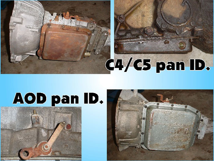
C4s came out in 1964 and ended with the 81 model. C4 pans have 11 bolts, are 10 by 9 and can have a 1 or 2 deep sump. Trucks and larger cars may have a pan with a treaded hole on the right side for the dipstick tube. C5 trannies started with the 82 model and ran through 86. It looks like the C4 but has a deeper bell housing (for the deeper internal clutch type converter), all have the 2 depth pan sump and use a fine tread front band adjusting screw. The C4/C5 has a bolt on bellhousing. AODs ran from 1980 to 93. AOD pans have 14 bolts, are about 14.5 by 13 with a 2 depth. 4x4s have a pan with a dropped center. AODs use a TV. (throttle valve) linkage on the left side that is hooked to the carburetor or throttle body with a cable or rod. It also uses a small round neutral switch above the TV. link which is screwed into the case. The AOD has a one piece alloy bellhousing and case.
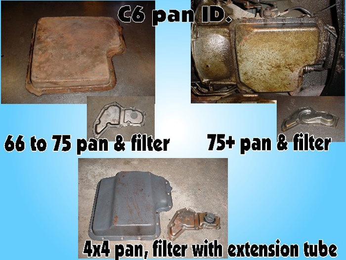
The C6 came out in 1966 (and was in some very late 65 police cars) and ended production in the mid 90's. C6s made from 66 to 75 have pans with 17 bolts, are about 14 by 13.5 with 1 to 1.5 depth. 75+ models have pans about 1.75 to 2 deep. 4x4 pans are 3 deep in the center and have an extension tube on the filter. The C6 has a one piece alloy bellhousing and case.
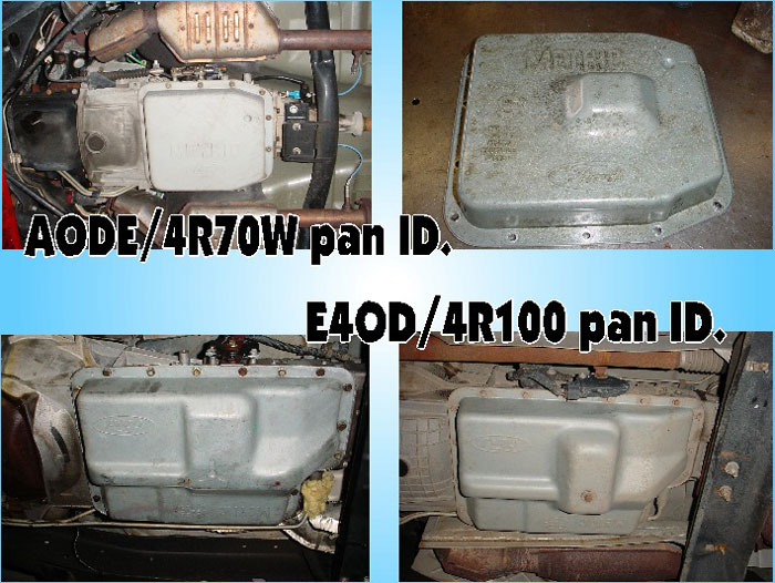
AODE/4R70W go from 92 to present. Its pan is similar to the AOD. These trannies have a large neutral switch (sometimes called a MLPS) mounted to the manual linkage and has a hole covered by a rubber plug on the bellhousings bottom. 4x4 truck pans (and 76+ model cars and 2wd trucks) are dropped near the center. The AODE/4R70W uses a one piece alloy bellhousing and case. E4OD pans are 20.5 by 13.5 with 20 bolts. The E4OD was used from 89 to 98. The 4R100 normally has a pan drain plug a was used from 98 to present. These trannies have a one piece alloy bellhousing and case.
Tips for Transmission Installation
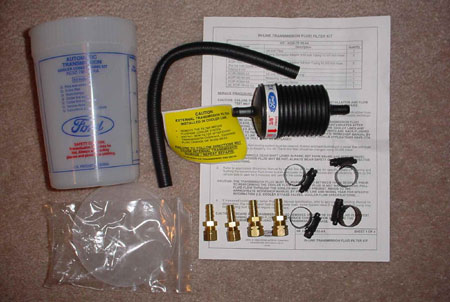
With the trans ready to go in, be sure the cooler lines are clean. Please be sure to wear safety glasses when your working. You may use a hose hooked to your parts cleaner to pump solvent through one cooler line and attach another hose to the remaining line back to the cleaner. Then blow out lines with compressed air (not more than 30 psi). I would highly recommend using a cooler line filter in the line going to the rear trans fitting. Be sure the filters arrow points to the rear fitting. Be sure you draw up the trans to the engine carefully. Do not bind up the converter. The converter should be loose in the flywheel with the trans fully bolted to engine. Make sure the down shift rod, manual linkage and neutral safety switch are adjusted right. Remember to install the vacuum hose on the modulator diaphragm. Before you start the engine, put 4 quarts of fluid in, put on parking brake, and I think its a good idea to put the rear end up on jack stands. Start engine, put another 4 or 5 quarts in then check with dipstick until you see fluid on the stick. Try putting trans in reverse and forward gears (may have to add more fluid if theres no engagement). Check fluid level again and add until it shows at the bottom of the crosshatch mark. Take car out for a road test to warm the fluid up and test shift quality. Back at the shop with car idling in park on level ground check fluid level and add if needed to indicate in cross hatch area. If you had trouble with delayed up shifts, 2nd or 3rd gear take off etc., more driving should clear that up. If it continues to have erratic shifts the valve body and governor are still sticking and may have to be removed and re-cleaned. The Ford XC3Z-7B155-AA cooler line filter kit below.
General Powerglide Info
1. The Aluminum Powerglide was produced from 1963 to 1973 with a limited
run in 62.
2. The PG was put in almost everything GM had from 4 cyl. Novas, to big
block Camaros, trucks, Vegas, you name it.
3. From 62 to 66, the PG had dual oil pumps to allow for push starting. In
1967, the rear pump was removed.
4. The much older (50s to early 60s) cast iron Powerglides do not have
interchangeable parts with the aluminum version.
5. The PG has the small block/big block Chevy bell housing bolt pattern.
Vegas and BOP (Buick, Oldsmobile Pontiac) had different bolt patterns.
6. There was a short lived option called a Torque Drive which was a manual
shift only.
7. Powerglides came in two first gear ratios. The 1.82, found in 4, 6 and
some 8 cyl. cars and the 1.76 normal seen in 8 cyl. cars and trucks.
|
|


Home |
Products |
Downloads Tools |
Trans FAQ's |
Rear FAQ's |
5.0L Swap FAQ's |
Testimonials |
Past Projects |
Contact | Links |
What's New
© Copyright Bad Shoe Productions
- All Rights Reserved